Published Book on Amazon
| All of IOT Starting with the Latest Raspberry Pi from Beginner to Advanced – Volume 1 | |
| All of IOT Starting with the Latest Raspberry Pi from Beginner to Advanced – Volume 2 |
출판된 한글판 도서
| 최신 라즈베리파이(Raspberry Pi)로 시작하는 사물인터넷(IOT)의 모든 것 – 초보에서 고급까지 (상) | |
| 최신 라즈베리파이(Raspberry Pi)로 시작하는 사물인터넷(IOT)의 모든 것 – 초보에서 고급까지 (하) |
Original Book Contents
25.5.2 Breadboard
25.5.2.1 Structure of Breadboard
The breadboard is a device where the 2.54mm spaced holes to allow wires to be inserted are placed in a lattice pattern on the front so that electronic components can be easily inserted and removed again.
The device below is a typical breadboard. The part where two red and blue lines are drawn vertically on the left and right is called a Bus area. It is usually used by connecting the power source. Connect the (+) power source to the red color and the negative (-) power source to the blue color. In the center, the part where is separated into two parts horizontally and consists of each 5 holes is called an IC (Integrated circuits) area. It is a place where various parts can be arranged. Both sides have small holes, so you can construct the circuit by inserting the legs of various parts.
The internal structure of the breadboard is as shown in the figure below, where electrically conductive metal wires connect these holes in rows and columns. Normally, the holes of Bus area on both sides are connected entirely in vertical length, and the holes of IC area in the middle is divided into left and right and connected by five in short horizontal width. Thus, it makes the electronic components of the same row/column to be connected to each other without using separate wires.
The breadboard is used to make test electric circuits by connecting it with the GPIO pins, and is a convenient tool to easily make and modify the test circuit without soldering by connecting the wires together on the board.
There are many kinds of breadboard depending on the usage and the sizes are various. An example of a breadboard is shown below.
Figure 25‑11 Breadboard overall shape Figure 25‑12 Internal connection shape
25.5.2.2 How to Use Breadboard
In the breadboard, it should be understood that the holes in the Bus area and the IC area are internally connected to each other, and care should be taken not to short internally.
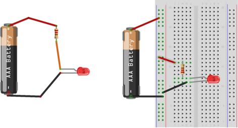
The following are circuits for turning on a LED lamp. The circuit on the left is connecting by soldering the battery and the resistor. The circuit on the right is connecting by inserting the part and the wire into the groove of the breadboard. In this way, with breadboard, you can easily make electronic circuits by inserting the legs of the electronic parts into the breadboard grooves without soldering.
The figure below shows the actual installation of several components on a breadboard.
|
|