Published Book on Amazon
| All of IOT Starting with the Latest Raspberry Pi from Beginner to Advanced – Volume 1 | |
| All of IOT Starting with the Latest Raspberry Pi from Beginner to Advanced – Volume 2 |
출판된 한글판 도서
| 최신 라즈베리파이(Raspberry Pi)로 시작하는 사물인터넷(IOT)의 모든 것 – 초보에서 고급까지 (상) | |
| 최신 라즈베리파이(Raspberry Pi)로 시작하는 사물인터넷(IOT)의 모든 것 – 초보에서 고급까지 (하) |
Original Book Contents
25.4.2 Series and Parallel of Resistance
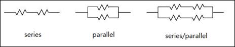
Basic resistance connections include a series connection where the combined resistance increases and a parallel connection where the combined resistance is reduced.There are three ways of connecting resistance: series connection, parallel connection and series/parallel connection.
25.4.2.1 Series Connection of Resistance
● Combined resistance of series connection
A series connection is a form in where the sum of the resistances increase, which the combined resistance is equeal to the sum of entire resistances.
|
|
That is, the combined resistance of the entire circuit is a sum of the respective resistance values, and the current flowing in the circuit is calculated as follows.
![]() R = R1 + R2 + R3
R = R1 + R2 + R3
● Current, voltage drop, and voltage distribution of series connection
A characteristic of the series connection is that the same current flows for each resistance, and the voltage drop across each resistance is proportional to the resistance value. When a voltage is applied to the circuit, the voltage is distributed in proportion to each resistance, and when summed, it equals the supplied voltage
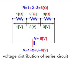
The total resistance of the circuit above is 6Ω, so the total current flowing in the circuit is 1 A. Since the current flowing in the circuit is 1 A, the voltage applied to each resistance is 1V, 2V, 3V. That is, the voltage is distributed in proportion to the resistance. The voltage 6V applied to the entire circuit is divided (distributed) in proportion to the magnitude of the three resistance, and the sum of the voltages is equal to the voltage of the entire circuit. When 6V is applied to the circuit, the voltage drop across each resistance is proportional to the value of the resistance.
● Working principle of ammeter
The ammeter is connected in series to the wire of the circuit. Figuratively explaining, it is the ammeter that measures the amount of water passing through a point at a given time.
25.4.2.2 Parallel Connection of Resistance
● Combined resistance of parallel connection
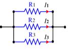
In the circuit below, three resistances are connected in parallel. Since the current flows through each resistance, it is divided into three currents, and the current is inversely proportional to the magnitude of the resistance. The combined resistance in a parallel connection is less than the smallest resistance. That is, the combined resistance of the entire circuit is calculated as follows.
|
|
When connected in parallel, the combined resistance is calculated as follows.
1/R = 1/R1 + 1/R2 + 1/R3
● Current, voltage, and current distribution in parallel connection
The basic feature of a parallel circuit is that the voltage across each resistance is the same and the current is different. In a circuit in which resistances are connected in parallel, the same voltage is applied to each resistance and the current flowing in the resistance flows in inverse proportion to the resistance. The current is divided by the number of connected resistances, and the current flowing through each resistance is obtained by the Ohm's law. The current flowing through the entire circuit is equal to the sum of the currents flowing through the resistances.
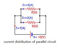
In the above, the entire combined resistance is R = 1 / (1/2 + 1/5) = 7Ω, and the voltage applied to each resistance is 10V. 7A current flows into the circuit, 10/2 = 5A flows into the resistance of 2Ω and 10/5 = 2A flows into the resistance of 5Ω, and the sum becomes 7A.
● Working principle of volmeter
The voltmeter is connected in parallel. In a figurative sense, it is the voltmeter that draws a very small fraction of a given stream and measures its velocity.
25.4.2.3 Why to Use Resistance
● Limiting current
If a voltage is constant, the current flowing in the line can be limited by resistance. The problem in the following circuit is that when the switch is off, no electricity flows, but when the switch is on, too much current flows from Vcc to GND. This can cause a lot of heat, which can burn parts and wires or cause a fire. Therefore, it is good to protect the circuit by using a suitable resistance to limit current so that a small current flows.
|
|
● Voltage distribution
If connecting resistances in series, the voltage can be distributed. In a series connection of resistances, the total current flowing into the circuit is determined by the combined resistance. The current flowing through each resistance is the same as the total current. On the other hand, the voltage drop across each resistance is distributed proportionally to the magnitude of the resistance.
|
|
● Current distribution
If resistances are connected in parallel, current can be distributed. In a parallel connection of resistances, the total current flowing into the circuit is determined by the combined resistance. The voltage across each resistance is equal to the total voltage. On the other hand, the current flowing through each resistance is distributed in inverse proportion to the magnitude of the resistance.
|
|