Published Book on Amazon
| All of IOT Starting with the Latest Raspberry Pi from Beginner to Advanced – Volume 1 | |
| All of IOT Starting with the Latest Raspberry Pi from Beginner to Advanced – Volume 2 |
출판된 한글판 도서
| 최신 라즈베리파이(Raspberry Pi)로 시작하는 사물인터넷(IOT)의 모든 것 – 초보에서 고급까지 (상) | |
| 최신 라즈베리파이(Raspberry Pi)로 시작하는 사물인터넷(IOT)의 모든 것 – 초보에서 고급까지 (하) |
Original Book Contents
25.2 GPIO Details
25.2.1 GPIO Device
25.2.1.1 GPIO Pin Layout
Since Raspberry Pi B+ model, Raspberry Pi board has a 40-pin GPIO connector with 2 male headers arranged on the left side of SD card slot. The spacing between each header is 2.54 mm (0.1 inches), which is one of the standard spacings used in electronics and is the standard spacing for prototyping platforms including stripeboard and breadboard.
The following is a picture of the GPIO Pin installed in Raspberry Pi.
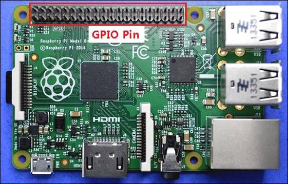
Figure 25‑1 Raspberry Pi GPIO pin
25.2.1.2 List and Function of GPIO Pin
The following is a summary of the individual names and functions of GPIO pins.
|
|
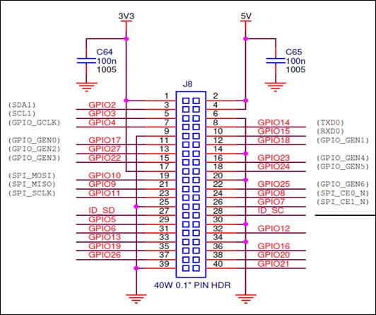
Figure 25‑2 Raspberry Pi GPIO pin layout 1
The following is a summary of the individual names and functions of GPIO Pins in different forms.
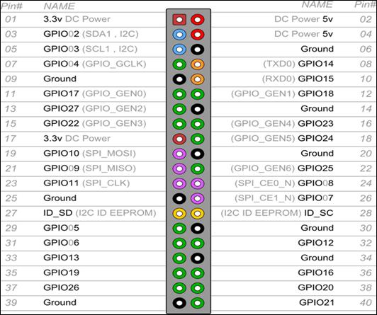
Figure 25‑3 Raspberry Pi GPIO pin layout 2
The following table summarizes GPIO pins in the order.
| Board | BCM IO | Function | Description |
| 1 | Power | 3.3V | |
| 2 | power | 5.0V |
|
| 3 | GPIO 2 | I2C SDA1 | Data. 1.8k pull-up resistor |
| 4 | power | 5.0V | |
| 5 | GPIO 3 | I2C SCL1 | Clock. 1.8k pull-up resistor |
| 6 | DNC | Ground |
|
| 7 | GPIO 4 | GPIO_GCLK |
|
| 8 | GPIO 14 | UART TXD0 | transmit |
| 9 | DNC | Ground |
|
| 10 | GPIO 15 | UART RXD0 | receive |
| 11 | GPIO 17 | GPIO_GEN 0 |
|
| 12 | GPIO 18 | GPIO_GEN 1 | PCM_CLK/PWM0 |
| 13 | GPIO 27 | GPIO_GEN 2 |
|
| 14 | DNC | Ground |
|
| 15 | GPIO 22 | GPIO_GEN 3 |
|
| 16 | GPIO 23 | GPIO_GEN 4 |
|
| 17 | Power | 3.3V | |
| 18 | GPIO 24 | GPIO_GEN 5 |
|
| 19 | GPIO 10 | SPI_MOSI | Master Out, Slave In |
| 20 | DNC | Ground |
|
| 21 | GPIO 9 | SPI_MISO | Master In, Slave Out |
| 22 | GPIO 25 | GPIO_GEN 6 |
|
| 23 | GPIO 11 | SPI_SCLK | Serial Clock |
| 24 | GPIO 8 | SPI_CE 0_N | Channel Enable 0. Slave Select (SS) |
| 25 | DNC | Ground |
|
| 26 | GPIO 7 | SPI_CE 1_N | Channel Enable 1. Slave Select (SS) |
| 27 | ID SD |
| I2C ID EEPROM |
| 28 | ID SC |
| I2C ID EEPROM |
| 29 | GPIO 5 |
|
|
| 30 | DNC | Ground |
|
| 31 | GPIO 6 |
|
|
| 32 | GPIO 12 |
| PWM0 |
| 33 | GPIO 13 |
| PWM1 |
| 34 | DNC | Ground |
|
| 35 | GPIO 19 |
| PCM_FS/PWM1 |
| 36 | GPIO 16 |
|
|
| 37 | GPIO 26 |
|
|
| 38 | GPIO 20 |
| PCM_DIN |
| 39 | DNC | Ground |
|
| 40 | GPIO 21 |
| PCM_Dout |
Table 25‑1 Raspberry Pi GPIO pin layout 3